Athena - Milestone 4
It’s been a while since I have written one of these so forgive me if I am a little out of practice. Unfortunately I do not remember so of the finer details about this milestone so I’ll be updating this post as things come back to me.
As I mentioned at the end of Milestone 3 I wanted Milestone 4 to be about setting up some very basic lighting to give the game some more life. So let’s begin!
Diffuse Lighting and Gourad Shading:
For our lighting model we are going to be using a diffuse lighting model. The basic definition of diffuse lighting is a lighting model that assumes light is reflected from a surface in many directions. The opposite of this would be a mirror which reflects light in one direction. For our diffuse model we are going to assume light is reflected evenly in all directions. No real world surfaces are like this but it is a good starting point for us. These assumptions with this lighting model means we will be using Lambertian Reflectance.
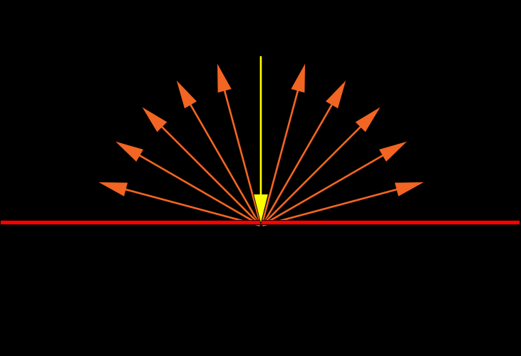
This is the basic idea of what Lambertian Reflectance should look like. A light hits a surface and is reflected evenly in all directions
The diffuse lighting equation is as follows:
R → Reflected Colour; the colour of light reflected from the surface being lit.
I → Lighting Intensity; a value representing the intensity and colour of the light hitting the surface
D → Diffuse Surface Absorption; a value representing the colour of the surface
θ → Angle of Incidence; the angle between the surface normal and the vector from the surface to the light
R = D · I · cos(θ)
∴ the reflected light is equal to the product of the colour of the surface, the colour and intensity of the light and cos of the angle of incidence. We use cos because it represent the perfect distribution of light that would be reflected.
i.e. when θ = 0° then cos(θ) = 1 so the light intensity is completely reflected and when θ = 90° cos(θ) = 0 so the light intensity is not reflected.
Normals and The Angle of Incidence:
Great so now we know how to calculate our lighting model but we are missing some pieces in order to do the actual calculation. Namely θ, the angle of incidence. In order to get this angle we are going to need two vectors. We know that all of our triangles face a direction we also know that this is called a normal/ surface normal. The good news is that we should have normals as part of our vertex data already since we already read in the data from the obj file in the last milestone! Now if only I had parsed the data correctly back then…
So back in Milestone 3 we pulled all the indices out of the obj file and only used the positions for drawing elements. We didn’t however do this for our normals or our UV coordinates yet. Here is where my memory is a little fuzzy I will make sure to write down my challenges and road blocks next time so if I go through a period of not writing again I can reference those notes. From what I remember we were still using indexed drawing in the last Milestone, this is great if we want to use pervertex normals. Unfortunately the obj files we were using had face normals and face normals do not work with index drawing. This is because if you have a vertex position that is used for 2 faces and if the faces point in different directions you will have 2 normals for that same vertex position.
Example:
Let’s say we have the face data below: (remember it is vertex/uv/normal for each point in the face and there are 3 points per face so each line is 1 face)
f 1/1/1 2/2/1 3/3/1
f 2/2/2 4/4/2 5/5/2
f 2/2/3 5/5/3 3/3/3
As you can see face 2 and 3 both start with vertex 2 BUT they have a different normal this is because this data is for a face normal
f 1/1/1 2/2/2 3/3/3
f 3/3/3 4/4/4 1/1/1
f 3/4/3 2/1/2 8/2/8
this data is for per vertex normals and you can see that faces 2 and 3 start with vertex 3 and normal 3 this is because each unique vertex has a unique normal associated with it
So you can’t have an index of i index into 2 different normal locations so this just isn’t going to work for face normals! This means we have 2 choices fix the import or export the obj files with vertex normals. Let’s do both!
I got Donna to export an obj file with per vertex normals and one with face normals so that I could see how to correctly import both types of data!
Per Vertex:
So given a list of positions, normals and uvs we want to be able to use one set of indices to index into each section of the data. So using the position indices we will index into a new fixed normals/uvs list at the position index and set the data to be the normal at the normal index that corresponds to the position index. It will probably be much clearer once we see it.
//you have positions in a buffer, positions[] size num_positions, position_indices[] size face_count and normals[] size num_normals,
//normal_indices[] size face_count

for (int i = 0; i < face_count; i++)
{
  new_normals[position_indices[i]] = normals[normal_indices[i]];
}
So for the above per vertex face data on the first iteration we index into new_normals at index 1 and set the data there to be the normal at index 1 from the list normals this will give us a new_normals list with some duplicate data but also allow us to use just the position indices when using DrawElements.
Face Normals:
For face normals you basically just want to strip away the indices we can do so like this:
// We will have loaded the following
Positions
Normals
UVs
PositionIndicies
NormalIndicies
UVIndicies
NumFaces

int DataCount = 0;
FinalDataArray;
FinalIndexArray;

for(int i = 0; i < faceCount; i++){

  FinalDataArray[DataCount++] = Positions[PositionIndicies[i]];
  FinalDataArray[DataCount++] = Normals[NormalIndicies[i]];
  FinalDataArray[DataCount++] = UVs[UVIndicies[i]];

  FinalIndexArray[i] = i;
}
so we just create 1 final data array from all positions, normals and uv’s used in the obj file, this duplicates a lot of data but unfortunately is a necessity to use face normals.
Now that our data is fixed we can pass it into our shaders as vertex attributes!
Direction To The Light
We still need our second vector in order to calculate our Angle of Incidence. This vector is going to be the vector from the surface to the light source. To make things simpler we will be using a directional light source. A directional light source is simple because it is basically what the name says it is, a direction and an intensity. Directional light sources are good for modelling things like the sun and other objects that are very far away so the direction from any point on the surface to the object is going to be pretty much the same.
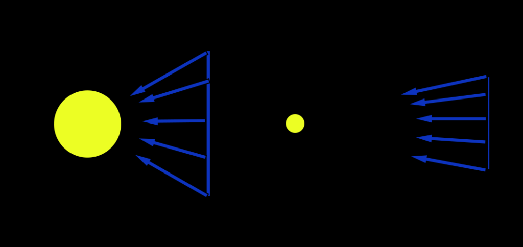
Even in this small example you can see the further the surface from the light source the less variation in their direction
This fact allows us to cheat a little and say our light source is infinitely far and so we can just pass in a single direction to our shader.
Angle of Incidence
Now that we have our surface normals added to our vertex data and a direction to the light source we pass everything into our vertex shader. This includes an intensity for the light source which can be passed in as a uniform. This is the simplest and most efficient way to compute lighting. Note that when we say simplest and most efficient we do not necessarily mean the best. Calculating lighting at the vertex and then letting the result be interpolated across the surface of the triangle is referred to as Gouraud Shading.
Now in our vertex shader we just need to calculate the angle of incidence and use our diffuse lighting equation.
Before we start we should figure out how we are going to calculate the angle! We know that given two vectors a and b that a · b = ||a|| · ||b|| · cos(θ)
∴ cos(θ) = a · b / ||a|| · ||b||
but the length of our normals and our direction to the light can be normalized before hand meaning they have a magnitude of 1
∴ cos(θ) = a · b
One issue you might face is that you need to have the normal and the vector for direction to the light in the same space for doing this equation I recommend camera space
Putting It All Together:
#version 330

layout(location = 0) in vec4 position;
layout(location = 1) in vec3 normal;
layout(location = 2) in vec3 uv;

smooth out vec4 interpColour;

uniform vec4 uniformDiffuseColour;
uniform vec3 dirToLight;
uniform vec4 lightIntensity;

uniform mat4 modelToCameraMatrix;
uniform mat3 normalModelToCameraMatrix;

layout(std140) uniform Projection
{
	mat4 cameraToClipMatrix;
};

void main() {
    gl_Position = cameraToClipMatrix * modelToCameraMatrix * position;

    vec3 normCamSpace = normalize(normalModelToCameraMatrix * normal);

    float cosAngIncidence = dot(normCamSpace, dirToLight);
    cosAngIncidence = clamp(cosAngIncidence, 0, 1);

    interpColour = (uniformDiffuseColour * lightIntensity * cosAngIncidence);
}
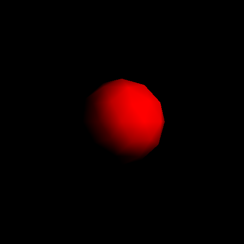
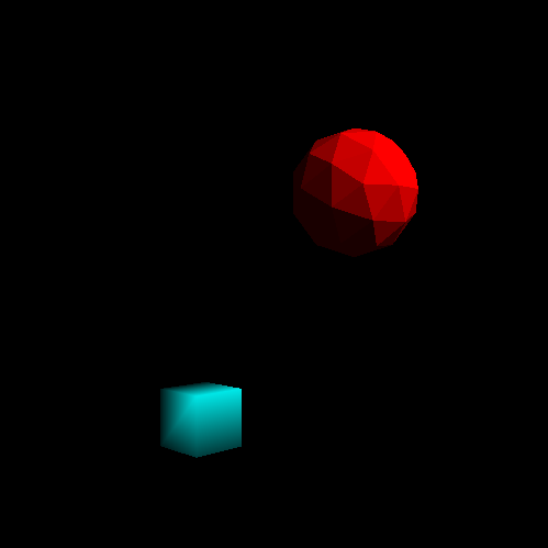
we get our first result!
and in motion!
Cool! We have lighting! But it looks bad. Really bad. It also looks nothing like the model we have been trying to import. What gives!
Well I’d like for you to look at this vertex data:
v 1.0000 1.0000 1.0000
v -1.0000 -1.0000 1.0000
v 1.0000 -1.0000 1.0000
Now, no matter what happens in my life, no matter how long I go without doing graphics programming, I will never forget this problem. It has been burned into my memory after multiple days of debugging and trying to figure out why my geospheres looked awful. For brevity I’ll skip to how I figured this out. After debugging for days making sure I was importing the data correctly. That I was passing in the values correctly. Learning multiple new techniques for debugging and inspecting memory I decided to become a renderer. I decide to draw the points out myself on a sheet of paper and see if I could notice something wrong. I did. If you’re interested you should take a moment to plot out those 3 simple points.
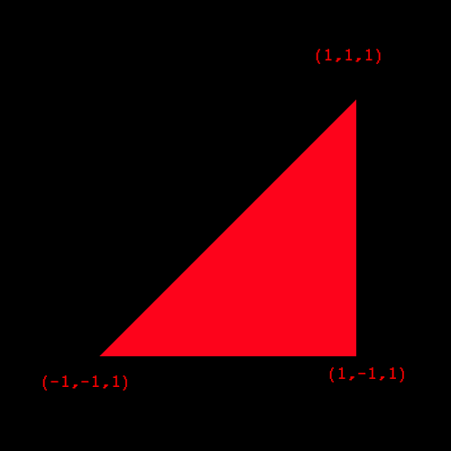
Notice anything wrong? It’s very easy to miss but notice the direction your hand is moving when you go from vertex 1, to 2, to 3.
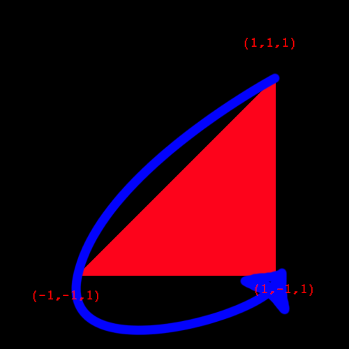
It’s counter clockwise! This means that it is going to be culled because when we initialized our renderer we said our front faces had clockwise winding order! This is why our geospheres look all messed up!
The good news is that this is easy to fix. Either export the models with clockwise winding order or set the front face to be counter clockwise winding order.
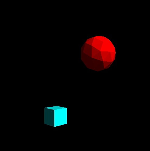
The results are now much better!
The cube is rendered with per vertex normals and the geosphere is rendered with face normals.
Something still doesn’t seem quite right though. The parts of our models that don’t reflect the light from the light source are completely black. That doesn’t look right at all. This is because in the real world objects are affected by interreflection. Interreflection is when the light from a light source gets reflected by a surface which is in turn reflected by other surfaces and so on until it reaches the eyes of the viewer. In graphics a model that handles interreflection is called global illumination. Global illumination is very hard and very complex so for now we will use a very easy approximation.
Ambient Lighting:
Ambient Lighting is a lighting model that models all contributions from interreflection as a single light intensity that doesn’t have an origin. It’s very easy to add ambient lighting to our current model all we need to do is pass in an ambient lighting intensity to our vertex shader and add it to our equation.
interpColour = (uniformDiffuseColour * lightIntensity * cosAngIncidence) + (uniformDiffuseColour * ambientIntensity);
The result looks pretty decent!
Face normal on the cube to show the difference to the per vertex render above
Put It All Together:
Conclusion:
That’s it for basic lighting! I think we did what we set out to do and made our game more vibrant and added a touch more realism to it while learning some great things by making great mistakes!
For those of you who don’t know I have started a new position at Vicarious Visions and I have been loving it! I’m working on some really great things and I can’t wait to eventually share it with all of you! Naturally this would mean I would be slowing down my pace for this project but working at Vicarious Visions has only made me more excited and more ready to push myself to learn how to make the things I want to bring to life and share with everyone! While I have only been sharing my technical learning process with you I want to share some of my design process as well. I have been working on a design for a game for awhile now and I want to begin talking about my process for that and the resources I have been using to better my design skills. So look out for that in the future.
For Milestone 5 we will be moving back to gameplay. We will be adding user input and adding some other gameplay features that will allow us to actually play the game. This is super exciting because at the end of Milestone 5 we will have made an actual game from scratch! There is a long way to go in making it look good and be fun but after Milestone 5 we will be able to say we made a game from scratch! Which is getting me super excited!